Cell Build Guide
Essential guidelines for optimal performance and safety when using electrolyzer research equipment
1. Fundamental Components of Electrolyzer Cell Hardware
An electrolyzer cell consists of a carefully engineered assembly of mechanical, electrical, and electrochemical components. Proper understanding of the role of each element is essential for reliable operation, performance optimization, and safety during testing. Figure 1 illustrates an exploded view of a typical single-cell hardware assembly.
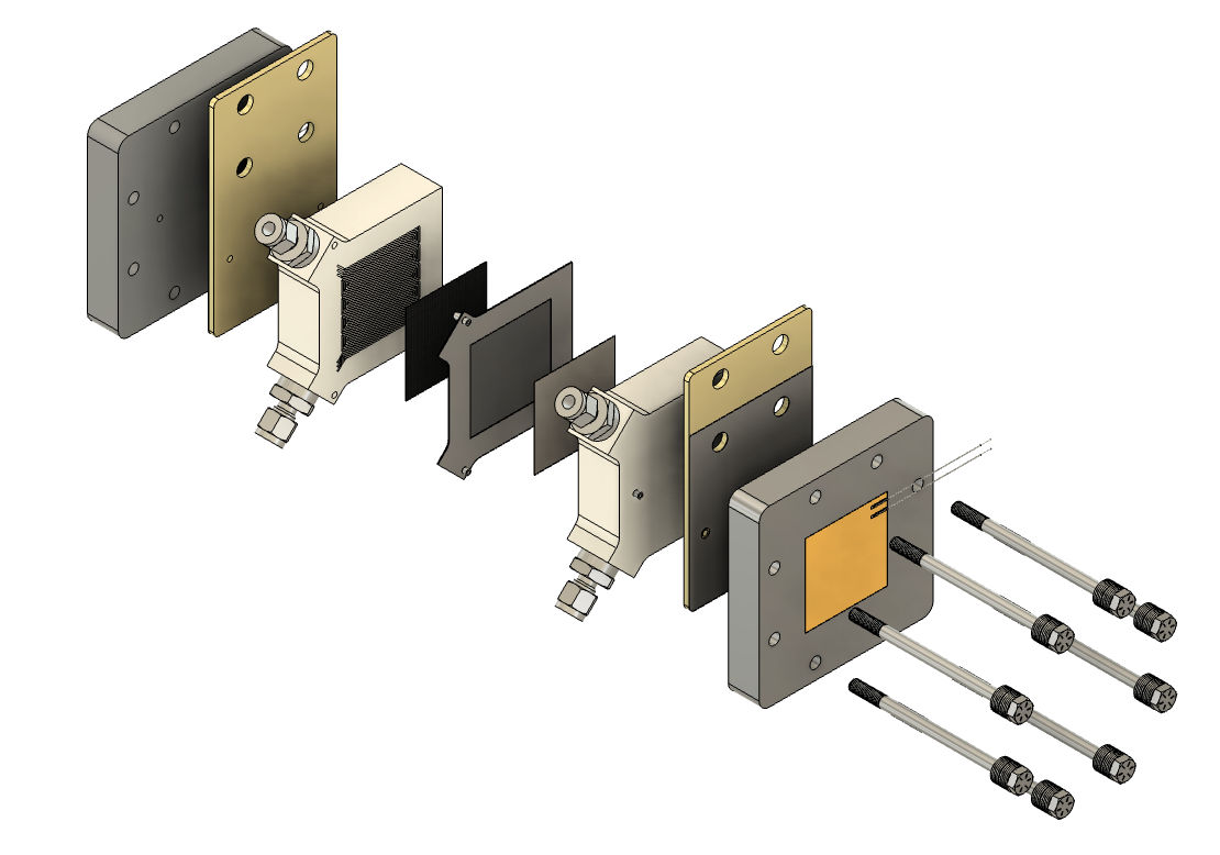
Figure 1: Exploded view of a typical single-cell hardware assembly showing the layered structure and components
a) Pressure Plates
Rigid metal plates that apply and maintain uniform mechanical compression across the cell. The applied load ensures consistent contact between functional layers, minimizes interfacial resistance, and prevents leakage.
b) Current Collectors
Highly conductive plates (commonly copper or coated stainless steel) positioned between the pressure plates and flow fields. Their primary function is to transmit current efficiently into the electrochemical cell while minimizing ohmic losses and contact resistance.
c) Flow Fields
Machined or molded plates containing channels designed to uniformly distribute water and gases (hydrogen and oxygen) across the active area. In addition to mass transport, flow fields conduct current and aid in thermal management by dissipating localized heat.
d) Gaskets
Sealing elements fabricated from chemically resistant elastomers or composites. They prevent cross-leakage of reactants and ensure mechanical integrity of the assembly under compression. Proper selection of gasket thickness and elasticity is critical for maintaining operational safety and long-term durability.
e) Porous Transport Layer (PTL)
A porous, conductive medium typically made of titanium felt on the anode side and carbon paper on the cathode side. The PTL promotes uniform distribution of water, facilitates gas evacuation, and provides an electrical pathway between the flow field and the catalyst layer.
f) Membrane Electrode Assembly (MEA)
The functional heart of the electrolyzer. It consists of a polymer electrolyte membrane coated with electrocatalyst layers and gas diffusion media. The MEA drives the electrochemical reaction, splitting water into hydrogen at the cathode and oxygen at the anode.
2. Guidelines for Assembling a High-Performance Electrolyzer Cell
The performance, reliability, and safety of an electrolyzer cell depend critically on proper assembly. Attention to detail in component alignment, torque application, and sealing integrity is required to avoid common operational issues such as gas crossover, excessive ohmic resistance, and premature degradation.
2.1 Optimization of Gasket and PTL Configuration
The relative thickness of gaskets and porous transport layers (PTLs) determines the compression and sealing behavior of the cell. A gasket that is too thin increases the risk of leakage, while a gasket that is too thick reduces compression in the active area, leading to poor electrochemical contact. The PTL thickness must be selected in conjunction with gasket dimensions to achieve uniform pressure distribution and proper fluid transport. Empirical testing and manufacturer guidelines should be followed when selecting these components.
2.2 Application of Controlled Compression
Mechanical compression is applied by tightening tie rods that secure the pressure plates. The applied torque must be calculated based on the mechanical properties of the components and validated experimentally to ensure both sealing and low contact resistance. Under-compression may result in gas leaks or poor electronic contact, whereas over-compression risks damaging the MEA or deforming the PTL. A calibrated torque wrench should always be used, and a uniform tightening sequence (commonly a star pattern) should be followed to avoid uneven loading.
3. Conditioning Protocols and Long-Term Stability
Electrolyzer cells are assembled at ambient temperature but are typically operated at elevated temperatures (60–80 °C or higher, depending on the design). Initial conditioning is required to activate the electrocatalysts, hydrate the membrane, and stabilize interfacial contact.
Standard conditioning protocols may include stepwise increases in current density, controlled temperature ramping, and intermittent operation to allow material relaxation. During long-term testing, thermal cycling caused by repeated startup and shutdown can relax the mechanical compression, leading to increased resistance or minor leakage. Therefore, periodic re-torque of tie rods is required to maintain sealing integrity and electrical performance. The frequency of re-torque should be established based on operational data and manufacturer recommendations.
Need More Help?
Have questions about implementing these best practices? Our technical team is here to help.